PRINCIPLE OF WORKING
In a three-phase induction motor, the stator is wound with a three-phase winding for P number of poles. The poles for which the winding is made could be 2, 4, 6, 8, … etc. The rotor which is placed inside the stator is either squirrel-cage type or slip-ring type. In both cases, current flowing through the three-phase stator winding produces a rotating magnetic field which will be rotating at a speed, Ns where
For a 50 Hz supply and P = 2, Ns is 3000 rpm. The rotating field will be rotating continuously at a very high speed. The rotating flux will cut the stationary rotor windings at that speed. Due to this cutting of flux, EMF will be induced in the rotor winding. As the rotor circuit has been made to be a closed winding, current will flow through the rotor-winding conductors. Thus the rotor circuit gets excited due to electromagnetic induction effect. Because of interaction between the current-carrying rotor conductors and the rotating magnetic field, torque will be developed in the rotor, which will rotate the rotor in the same direction as the rotating magnetic field at a speed Nr.
Parts of Induction Motor
It has got 2 main parts. Stator and Rotor. Stator is the stationery part and rotor is the rotating part. Rotor sits inside stator. There will be a small gap between rotor and stator, known as air-gap. Value of radial air-gap may vary from 0.5 to 2 mm.
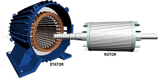 |
| Fig.1 Stator and Rotor of an induction motor |
Construction details of Stator
Stator is made by stacking thin-slotted highly permeable steel laminations inside a steel or cast iron frame. The way steel laminations are arranged inside frame is shown in following figure. Here only few of the steel laminations are shown. Winding passes through slots of stator.
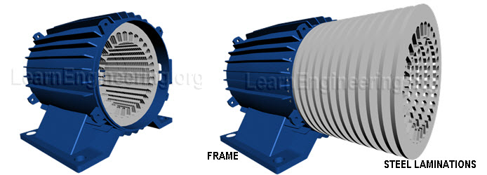 |
| Fig.2 Construction details of stator |
Effect of 3 Phase Current Passing Through Stator Winding
When a 3 phase AC current passes through the winding, something very interesting happens. It produces a rotating magnetic field. As shown in figure below a magnetic field is produced which is rotating in nature.
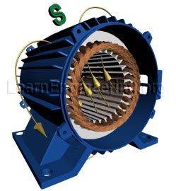 |
| Fig.3 Rotating magnetic field produced in an induction motor |
Concept of Rotating Magnetic Filed
To understand this phenomenon much better consider a simplified 3 phase winding with just 3 coils. A wire carrying current produces magnetic field around it. Now for this special arrangement magnetic field produced by 3 phase A.C current will be as shown at a particular instant.
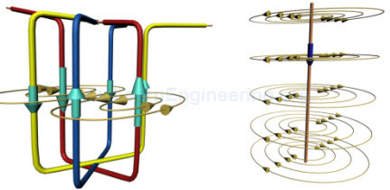 |
| Fig.4 Magnetic field produced around the simplified winding and a single wire |
With variation in A.C current, magnetic field takes a different orientation as shown. From these 3 positions it’s clear that, it is like a magnetic field of uniform strength rotating. Speed of rotation of magnetic field is known as synchronous speed.
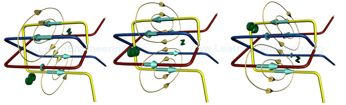 |
| Fig.5 Rotating magnetic field produced over simplified winding |
Effect of RMF on a Closed Conductor
Assume you are putting a closed conductor inside it. Since the magnetic field is fluctuating an e.m.f will be induced in the loop according to Faraday’s law. The e.m.f will produce a current through the loop. So the situation has become like a current carrying loop is situated in a magnetic field. This will produce magnetic force in loop according to Lorentz law. So loop will start rotating.
 |
| Fig.6 Effect of RMF on a closed conductor |
Working of Induction Motor
A similar phenomenon happens inside induction motor also. Here instead of simple loop something very similar to a squirrel cage is used.
 |
| Fig.7 Squirrel cage rotor which is the most commonly used one in induction motors. |
3 phase AC current passing through stator winding produces a rotating magnetic field. So as in previous case, current will be induced in bars of squirrel cage which is shorted by end rings and it will start rotating. You can note variation of current induced in squirrel cage bars. This is due to rate of change of magnetic flux in one squirrel bar pair is different from another, due to its different orientation. And this variation of current in bar will change over time.
 |
| Fig.8 RMF produces a torque on rotor as in the simple winding case |
That’s why the name induction motor, electricity is induced in rotor by magnetic induction rather than direct electric connection. To aid such electromagnetic induction insulated iron core lamina are packed inside the rotor.
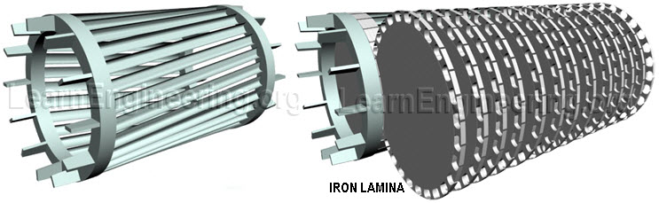 |
| Fig.9 Thin layers of iron lamina which are packed in rotor |
Such small slices of iron layers make sure that eddy current losses are minimum. You can note one big advantage of 3 phase induction motors, it is inherently self starting.
You can also note that bars of squirrel cage are inclined to axis of rotation, or it has got a skew. This is to prevent torque fluctuation. If bars were straight, then there would be a small time gap for the torque in rotor bar pair to get transferred to the next pair. This will cause torque fluctuation and vibration in rotor. By providing a skew in rotor bars, before torque in one bar pair gets over next pair comes into action. Thus avoids torque fluctuation.
Speed of Rotation of Rotor & Concept of Slip
So you can notice here that, both magnetic field and rotor are rotating. But at what speed rotor will rotate?.To obtain answer for this lets consider different cases.
Consider a case where rotor speed is same as magnetic field speed. Since both are rotating at same speed, rotating loop will always experience constant magnetic field. So there won’t be any induced e.m.f and current. This means zero force on rotor bars. So rotor will gradually slow down.
But as it slows down, rotor loops will experience a varying magnetic field, so induced current and force will rise again. And rotor will speed up.
In short, rotor will never be able to catch up with speed of magnetic field. It rotates at a specific speed which is slightly less than synchronous speed. Difference in synchronous and rotor speed is known as slip.
Energy Transfer in Motor
Rotational mechanical power is transferred through a power shaft. In short in an induction motor, electrical energy is entered via stator and output from motor, mechanical rotation is received from rotor.
 |
| Fig.10 Power transfer in a motor |
Energy loss during motor operation is dissipated as heat. So a fan at other end helps in cooling down the motor.
 |
| Fig.11 A cooling fan is used to remove heat liberated by motor |
